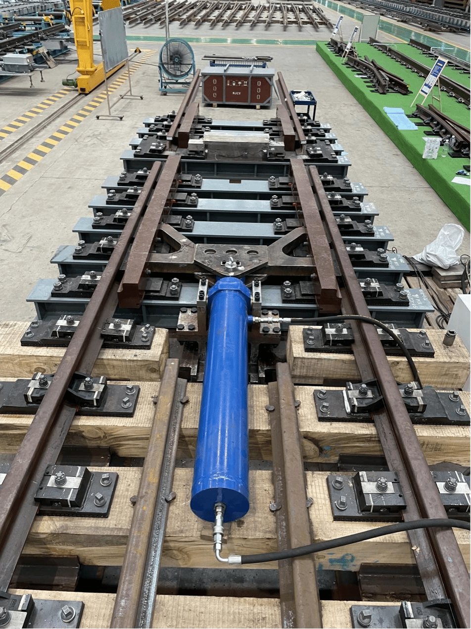
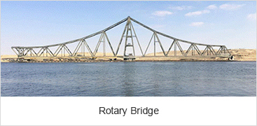
54E1 Rail 1435mm Gauge One-way Expansion Device is specifically designed for Suez Canal Ferdan Bridge in Egypt, the project include 2 bridges: the old bridge upgrading, new bridge construction, total 12 sets of rail expansion device. CRBBG is involved in this project for design, manufacture and supply, as well as on site installation. The device will be used on the joint of the rotary bridge butt to keep the precise link and sooth running of the train at max speed 70km/h.


1. Technical parameters
Bridge: Steel bridge with two span (320m long each span)
Gap: 450±120mm when the turn bridge is closed
Rail: 54E1 profile, 1:20 rail cant
Track gauge: 1435mm, measured at 14mm below rail top surface
Wheel: Type LM wheel
Load axle: 26t
Speed: 70km/h
Foundation under rail: Ballastless
The rail expansion device mainly divided into 3 parts: rail system, locking system and hydraulic actuation. To make sure the safety and reliable and smooth running, CRBBG team did adequate wok to analyse the whole system, such as the wheel and rails, sleeper gauge, locking ways and so on through tools like ANSYS.


1. Geometry
The expansion device in this project adopts the structure that the switch rail is locked and the stock rail is expanded under an external force. When the turn bridge is closed, the stock rail is extended by the hydraulic driving device, and its extended end is connected with the track on the other side to allow the train to pass; when the turn bridge is opened, the stock rail is retracted under the external force to be closed to traffic and allow the boats and vessels to pass.
The close contact edges of stock rail and switch rail ensure the gauge cannot change during the expansion of stock rail. The stock rail is 11900mm long and the switch rail is 8800mm long. The designed maximum expansion is 860mm, the total length of expansion device is (13235~14025) mm, and the temperature range of the product is -4℃ to 52℃.
2. Rails
The stock rail is made of 54E1 rail, grade R350HT and is designed with 1:20 rail cant.
The switch rail is made of 54E1A1 rail, and its end is forged to standard 54E1 rail. The switch rail is designed with 1:20 rail cant.
3. Iron plates
The iron plate is welded using Q235-B steel plates. The upper surface of the plate is machined to 1:20 slope. The surface that bears the stock rail is subjected to anti-friction treatment to reduce the longitudinal expansion resistance.
4. Fastenings
Rail braces: divided into stock rail brace and switch rail brace, which are made of steel QT450-10. Rail brace is connected with the plate by bolts. The clearance between the stock rail brace and the upper surface of rail leg and the rail web is (0.1~1) mm to ensure the normal expansion of stock rail. The switch rail brace shall be in full contact with the upper surface of rail leg and the rail web to increase the resistance and ensure the stability of switch rail.
Anti-friction fastenings: the anti-friction gusset plates are arranged at intervals in stock rail brace. The ultra-high molecular weight polyethylene (UHMWPE) pad is set at the pressing part of the gusset plate to reduce the longitudinal expansion resistance.
5. Heel of stock rail
The double rail brace structure is adopted at the heel of stock rail, to ensure stable structure and accurate guidance during the expansion of stock rail.
6. Expansion joints
Expansion joint is arranged at the joint, and is composed of guide link block, distance block and bolt. The guide link block and distance block are made of steel Q355. The adjustment shims are provided at the outside of distance block to adjust the flangeway width between stock rail and guide link block.
The mounting hole for expansion mechanism is reserved on the guide link block of expansion joint. The flangeway width between the guide link block and the running edge of stock rail is reserved according to the wheel tread, and its top is 12mm higher than stock rail top. When the stock rail is extended to connect with the track, it can not only improve the strength of the track, but also play a role of check rail, to ensure the safe running of the train.
7. Alignment device
Considering that there are lateral errors of 5mm and vertical errors of 2mm in the process of bridge rotation, in order to eliminate rail staggering after the track is connected, a flared type gusset plate is installed at the fixed beam end, to ensure the stock rail can be aligned with the track at the fixed end during the expansion of stock rail to improve the smoothness of the track.
There are total 30 sleepers, including 21 wooden sleepers with a length of 2.6m long and a sectional size of 250mm×200mm, and 9 steel sleepers with I-section and with a length of 2.6m long and a sectional height of 200mm. Of which, the width of upper flange plate of 2 steel sleepers is 300mm, and the width of upper and lower flange plates of the rest steel sleepers are 250mm. The thickness of flange plate and web plate is 20mm, the stiffeners are set between flange plate and web plate to ensure the strength and stability of steel sleepers.